NOR gate
High only when every input is low.
NOR gate truth table
| a | b | Q |
|---|---|---|
| 0 | 0 | 1 |
| 0 | 1 | 0 |
| 1 | 0 | 0 |
| 1 | 1 | 0 |
At a glance
- Boolean expression
- ¬(a ∨ b)
- Engineering notation
- (a + b)'
- Inputs
- Two or more
- Output is high when
- every input is low
NOR gate symbol
The ANSI NOR symbol is the OR shape, curved back and pointed front, with a bubble on the output. The bubble means inversion, so the symbol reads as OR followed by NOT. The IEC version is the OR rectangle, labelled ≥1, with a bubble on its output. The logic gate symbols page draws all seven gates side by side in both standards.
How the NOR gate works
A NOR gate outputs 1 only when all of its inputs are 0. Any input going high drops the output to 0. It is an OR gate with the output inverted.
Like NAND, NOR is functionally complete, so it can build every other gate on its own. It is also the gate behind the classic SR latch: two NOR gates each feeding the other's input, which is the first circuit most people meet that has memory rather than just combinational behaviour.
3-input NOR gate truth table
A 3-input NOR gate is the inverse of a 3-input OR: its output is 1 only when all three inputs are 0. Feeding one 2-input NOR into another does not give this, because the first inversion gets carried into the second gate. To widen a NOR from 2-input parts, OR the first two inputs and feed that into a NOR with the third.
| a | b | c | Inputs at 1 | Q |
|---|---|---|---|---|
| 0 | 0 | 0 | 0 | 1 |
| 0 | 0 | 1 | 1 | 0 |
| 0 | 1 | 0 | 1 | 0 |
| 0 | 1 | 1 | 2 | 0 |
| 1 | 0 | 0 | 1 | 0 |
| 1 | 0 | 1 | 2 | 0 |
| 1 | 1 | 0 | 2 | 0 |
| 1 | 1 | 1 | 3 | 0 |
Two 2-input NOR gates in a chain, !(!(a | b) | c),
do not give this table:
they differ from it on rows 000, 010, 100 and 110,
and work out to
(a | b) & !c. From 2-input parts, the 3-input gate is
!((a | b) | c).
NOR compared with the other gates
The same four input rows through every gate, with the NOR column highlighted. NOT has only one input, so its column is NOT a and ignores b.
| a | b | AND | OR | NAND | NOR | XOR | XNOR | NOT a |
|---|---|---|---|---|---|---|---|---|
| 0 | 0 | 0 | 0 | 1 | 1 | 0 | 1 | 1 |
| 0 | 1 | 0 | 1 | 1 | 0 | 1 | 0 | 1 |
| 1 | 0 | 0 | 1 | 1 | 0 | 1 | 0 | 0 |
| 1 | 1 | 1 | 1 | 0 | 0 | 0 | 1 | 0 |
- NOR is the exact opposite of OR on every row.
- NOR and XNOR are both 1 when both inputs are 0, and differ only on 11, where XNOR gives 1 and NOR gives 0.
Building the NOR gate from other gates
Each of these is equivalent to the NOR gate. Paste any of them into the simulator with ctrl+E to see the circuit.
| Construction | Expression | Equals |
|---|---|---|
| NOT from NOR | !(a | a) | !a |
| OR from NOR | !(!(a | b) | !(a | b)) | a | b |
| AND from NOR | !(!(a | a) | !(b | b)) | a & b |
| De Morgan form | !a & !b | !(a | b) |
NOR gate transistor circuit
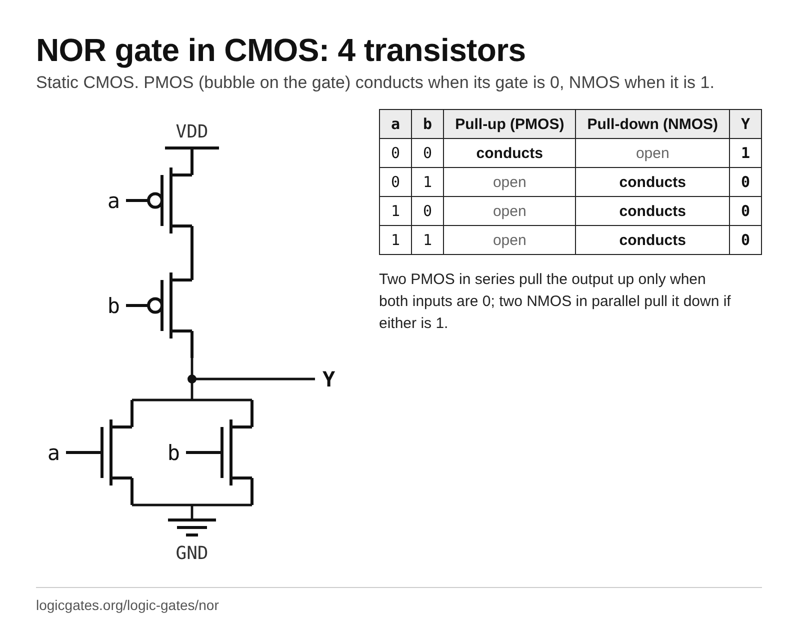
In static CMOS, the textbook NOR gate is a handful of transistors. Toggle the inputs to see which ones switch on and which network connects the output to the supply or to ground.
The pull-up network conducts (the PMOS transistors driven by a and b are on) and the pull-down network is open, so Y is connected to VDD and is 1.
Two PMOS in series pull the output up only when both inputs are 0; two NMOS in parallel pull it down if either is 1. PMOS transistors, drawn with a bubble on the gate, conduct when their gate is 0; NMOS conduct when it is 1.
NOR gate chip: the 7402 pinout
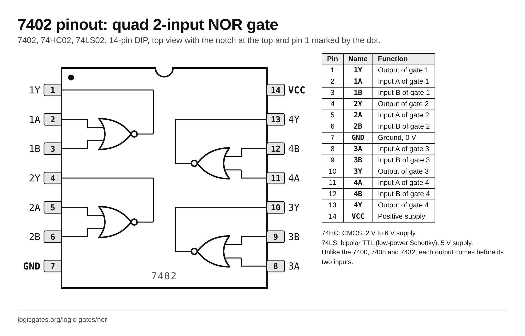
To build with real parts, the NOR gate comes four to a package in the 7400 series. The 7402 is a quad 2-input NOR gate.
7402, 74HC02, 74LS02: quad 2-input NOR gate, 14-pin DIP
| Pin | Name | Function |
|---|---|---|
| 1 | 1Y | Output of gate 1 |
| 2 | 1A | Input A of gate 1 |
| 3 | 1B | Input B of gate 1 |
| 4 | 2Y | Output of gate 2 |
| 5 | 2A | Input A of gate 2 |
| 6 | 2B | Input B of gate 2 |
| 7 | GND | Ground, 0 V |
| 8 | 3A | Input A of gate 3 |
| 9 | 3B | Input B of gate 3 |
| 10 | 3Y | Output of gate 3 |
| 11 | 4A | Input A of gate 4 |
| 12 | 4B | Input B of gate 4 |
| 13 | 4Y | Output of gate 4 |
| 14 | VCC | Positive supply |
- 74HC: CMOS, 2 V to 6 V supply.
- 74LS: bipolar TTL (low-power Schottky), 5 V supply.
- Unlike the 7400, 7408, 7432 and 7486, inputs and outputs trade places: the outputs are on pins 1, 4, 10 and 13 instead of 3, 6, 8 and 11.
NOR gate examples
Everyday and engineering things that follow the NOR rule.
- An "all clear" lamp on an alarm panel that is lit only while no alarm input is active: any one alarm turns it off.
- NOR flash memory, which holds the firmware of many motherboards and embedded devices, is named after the NOR-like way its cells are wired in parallel.
- The 7402 in the classic 7400 logic family holds four 2-input NOR gates in one package.
Where the NOR gate is used
- Cross-coupled pairs form an SR latch, the building block of flip-flops and registers.
- Detecting that a bus or a set of flags is completely idle, since NOR is high only when everything is low.
- Building any other gate, in the same way NAND can.
- The Apollo Guidance Computer was famously built almost entirely from three input NOR gates.
NOR gate reference card
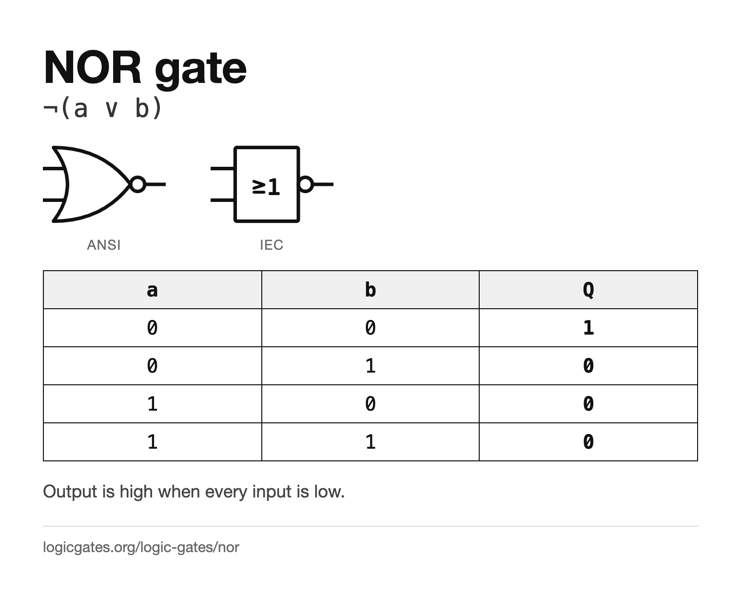
The symbol in both standards and the truth table on one image, for notes or a slide.
 Click to download the NOR reference card
In the simulator
NOR is in the Logic menu with a configurable input count. Wire two of them into each other, output to input, and you have a latch you can set and reset.
Questions about the NOR gate
What does a NOR gate do?
It outputs 1 only when all of its inputs are 0. If any input is 1 the output is 0. It is an OR gate followed by a NOT.
What is the symbol for a NOR gate?
The OR symbol, curved back and pointed front, with an inversion bubble on the output. In the IEC style it is a rectangle labelled ≥1 with the bubble on its output.
Why is NOR called a universal gate?
Because NOT, OR and AND can each be built from NOR gates alone, and those three can express any boolean function. So any circuit at all can be rewritten using only NOR gates.
How do you build an SR latch from NOR gates?
Take two NOR gates and feed each gate's output into one input of the other. The remaining free inputs become set and reset. Raising set drives one output high and it stays there after set returns low, which is what makes it a memory element.
What is the difference between NOR and NAND?
NOR outputs 1 only when all inputs are 0; NAND outputs 0 only when all inputs are 1. So NOR is 1 on just one of its four rows and NAND on three. Invert every input and the output of a NAND and you get a NOR, which is De Morgan's law in gate form. Both are universal.
Is NOR or NAND better for building everything?
Both are universal, so either works. In practice NAND is preferred in CMOS because it is slightly faster and smaller for the same drive strength, but NOR-only designs have been built, most famously the Apollo Guidance Computer.