XNOR gate
High when its two inputs agree.
XNOR gate truth table
| a | b | Q |
|---|---|---|
| 0 | 0 | 1 |
| 0 | 1 | 0 |
| 1 | 0 | 0 |
| 1 | 1 | 1 |
At a glance
- Boolean expression
- ¬(a ⊻ b)
- Engineering notation
- (a ⊕ b)'
- Inputs
- Two or more
- Output is high when
- its two inputs are equal
XNOR gate symbol
The ANSI XNOR symbol is the XOR shape, OR with the extra curved line at the inputs, plus a bubble on the output to mean inversion. IEC draws it as a rectangle labelled =, the sign for logic identity: the output is 1 when the inputs are equal. A =1 rectangle with an inverted output is also seen, and for two inputs the two mean the same thing. The logic gate symbols page draws all seven gates side by side in both standards.
How the XNOR gate works
An exclusive NOR gate outputs 1 when its two inputs are the same, both 0 or both 1, and 0 when they differ. It is an XOR gate with the output inverted, which makes it a one bit equality detector. Because of that it is also called the equivalence gate, and written a ≡ b or a ⊙ b.
Where XOR asks "are these two different?", XNOR asks "are these two the same?". That is the question an equality comparator, such as the tag match in a cache, asks of every pair of bits, so it is a row of XNOR gates feeding an AND. XNOR is not universal though: chain XORs and XNORs however you like and the result still only ever counts whether an odd or even number of some of its inputs are high, so AND and OR are out of reach without another gate.
3-input XNOR gate truth table
A 3-input XNOR gate is the inverse of a 3-input XOR: its output is 1 when an even number of inputs are 1, counting none as even. That makes it an even parity gate. Chaining two 2-input XNOR gates does not give this: the two inversions cancel, so a XNOR b XNOR c is the same as a XOR b XOR c, the odd parity function. To build the even parity version, chain XOR gates and invert once at the end.
| a | b | c | Inputs at 1 | Q | All equal |
|---|---|---|---|---|---|
| 0 | 0 | 0 | 0 | 1 | 1 |
| 0 | 0 | 1 | 1 | 0 | 0 |
| 0 | 1 | 0 | 1 | 0 | 0 |
| 0 | 1 | 1 | 2 | 1 | 0 |
| 1 | 0 | 0 | 1 | 0 | 0 |
| 1 | 0 | 1 | 2 | 1 | 0 |
| 1 | 1 | 0 | 2 | 1 | 0 |
| 1 | 1 | 1 | 3 | 0 | 1 |
Two 2-input XNOR gates in a chain, !(!(a ^ b) ^ c),
do not give this table:
they give its exact opposite on every row,
and work out to
a ^ b ^ c. From 2-input parts, the 3-input gate is
!((a ^ b) ^ c).
The IEC label = means all inputs are equal. For two inputs that is XNOR, but with three it is a different function, 1 only for 000 and 111. In the table, the "all equal" column differs from Q on rows 011, 101, 110 and 111.
XNOR compared with the other gates
The same four input rows through every gate, with the XNOR column highlighted. NOT has only one input, so its column is NOT a and ignores b.
| a | b | AND | OR | NAND | NOR | XOR | XNOR | NOT a |
|---|---|---|---|---|---|---|---|---|
| 0 | 0 | 0 | 0 | 1 | 1 | 0 | 1 | 1 |
| 0 | 1 | 0 | 1 | 1 | 0 | 1 | 0 | 1 |
| 1 | 0 | 0 | 1 | 1 | 0 | 1 | 0 | 0 |
| 1 | 1 | 1 | 1 | 0 | 0 | 0 | 1 | 0 |
- XNOR is the exact opposite of XOR on every row.
- XNOR is AND with one extra 1, on row 00. AND needs both inputs to be 1, while XNOR only needs them to be equal, which makes XNOR the equality gate.
Building the XNOR gate from other gates
Each of these is equivalent to the XNOR gate. Paste any of them into the simulator with ctrl+E to see the circuit.
| Construction | Expression | Equals |
|---|---|---|
| XOR, inverted | !(a ^ b) | (a & b) | (!a & !b) |
| Sum of products | (a & b) | (!a & !b) | !(a ^ b) |
| Product of sums | (a | !b) & (!a | b) | !(a ^ b) |
| XOR with one input inverted | a ^ !b | !(a ^ b) |
| From NAND gates only | !(!(a & !(a & !(b & b))) & !(!(b & b) & !(a & !(b & b)))) | !(a ^ b) |
XNOR gate transistor circuit
In static CMOS, the textbook XNOR gate is a handful of transistors. Toggle the inputs to see which ones switch on and which network connects the output to the supply or to ground.
NOT a: the pull-up network conducts (the PMOS driven by a is on) and the pull-down network is open, so ¬a is connected to VDD and is 1.
NOT b: the pull-up network conducts (the PMOS driven by b is on) and the pull-down network is open, so ¬b is connected to VDD and is 1.
XNOR: the pull-up network conducts (the PMOS transistors driven by a and b are on) and the pull-down network is open, so Y is connected to VDD and is 1.
The complementary design: two inverters make ¬a and ¬b, and an 8-transistor stage pulls the output down when the inputs differ and up when they agree, 12 transistors in all. PMOS transistors, drawn with a bubble on the gate, conduct when their gate is 0; NMOS conduct when it is 1.
XNOR gate chip: the 74LS266
To build with real parts, the XNOR gate comes four to a package in the 7400 series. The 74LS266 is a quad 2-input XNOR gate.
74HC7266, 74LS266: quad 2-input XNOR gate, 14-pin DIP
The pin diagram is not shown here. Check the manufacturer's datasheet for the exact part you have before wiring it: VCC and GND are on pins 14 and 7, but the gate pins are not laid out as on the 7400.
- 74HC7266: CMOS, 2 V to 6 V supply.
- 74LS: bipolar TTL (low-power Schottky), 5 V supply.
- The 74LS266 has open-collector outputs: each output needs a pull-up resistor to VCC to give a high level.
XNOR gate examples
Everyday and engineering things that follow the XNOR rule.
- Two-way light switches on a staircase, read the other way round from XOR: label the switch positions so the light is on when both switches point the same way, and the light is the XNOR of the two switches.
- A system with two identical sensors, such as the duplicated sensors in many safety systems, treats their readings as healthy while they agree and flags a fault when they differ. The "agree" signal is an XNOR.
- Content-addressable memory, used in network routers to look up addresses, compares a search word against every stored word at once, and each bit of that comparison is a match test like XNOR.
Where the XNOR gate is used
- One bit of an equality comparator: a XNOR per bit pair, then an AND across them, says whether two words are identical.
- The final stage of an even parity checker: XOR the data bits together, then XNOR the result with the received parity bit: the output is high when they match, so a 0 means an odd number of bits were flipped. Two flipped bits cancel out and go unnoticed, which is the limit of a single parity bit.
- A controlled buffer: XNOR a signal with 1 to pass it unchanged, or with 0 to invert it, the opposite sense to XOR.
- Counting matching bits between two patterns, which is how correlators and binary neural networks score a match: XNOR each pair, then count the 1s.
XNOR gate reference card
The symbol in both standards and the truth table on one image, for notes or a slide.
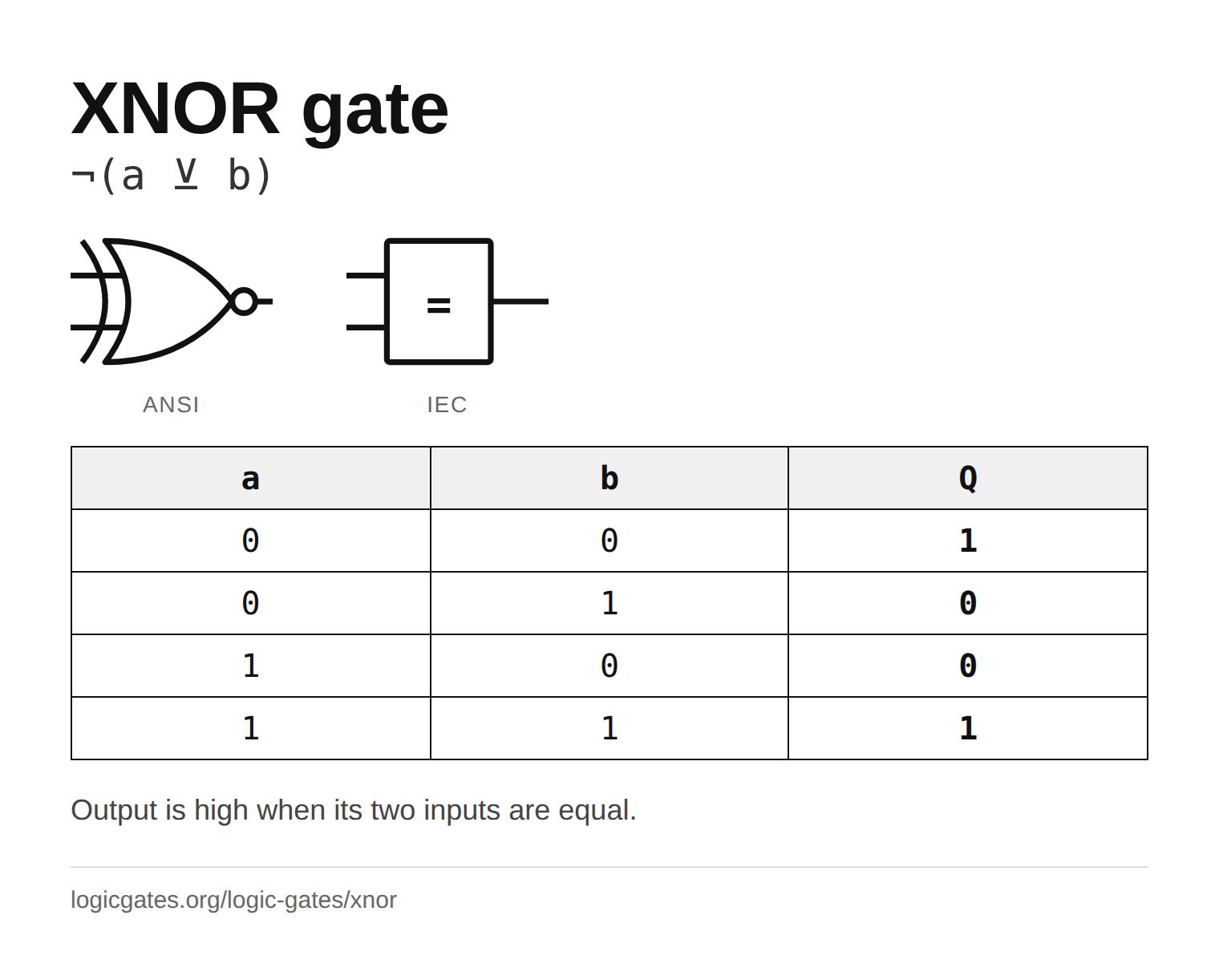 Click to download the XNOR reference card
In the simulator
There is no XNOR node in the simulator. Place an XOR and feed its output into a NOT, or put the NOT on one of the XOR inputs instead, which gives the same table. Package the pair as a custom node and it behaves like a native gate.
Questions about the XNOR gate
What is the difference between XOR and XNOR?
They are opposites on every row. XOR outputs 1 when its two inputs differ; XNOR outputs 1 when they are the same. XNOR is exactly an XOR gate followed by a NOT gate, which is what the N in the name and the bubble on the symbol mean.
What is the symbol for an XNOR gate?
In the ANSI style it is the XOR symbol with an inversion bubble on the output. In the IEC style it is a rectangle labelled =, or a =1 rectangle with an inverted output.
What does an XNOR gate do with three inputs?
A 3-input XNOR gate is the inverse of a 3-input XOR: it outputs 1 when an even number of inputs are 1, including none. Two 2-input XNOR gates in a chain give odd parity instead, because the two inversions cancel.
Is XNOR a universal gate?
No. NAND and NOR can each build every other gate, but XNOR cannot, and neither can XOR. Any circuit made only of XOR and XNOR gates still only reports whether an even or odd number of some of its inputs are high, however it is wired, so it can never behave like an AND or an OR. Add an AND gate to XOR and XNOR together and the set becomes complete: XNOR of a signal with itself supplies a constant 1, and XOR with 1 is NOT.
How many NAND gates does XNOR need?
Five. XOR takes four NAND gates, and XNOR is XOR with either the output or one of the inputs inverted, which is one more NAND with its inputs tied together. That is one more than XOR and three more than AND, so in NAND-only designs an equality test is comparatively expensive.
Why is XNOR called the equivalence gate?
Because its output is 1 precisely when the two inputs are equivalent, both 0 or both 1. In logic notation that is a ≡ b or a ⊙ b, and in a comparator that is the "these two bits match" signal.