OR gate
High when at least one input is high.
OR gate truth table
| a | b | Q |
|---|---|---|
| 0 | 0 | 0 |
| 0 | 1 | 1 |
| 1 | 0 | 1 |
| 1 | 1 | 1 |
At a glance
- Boolean expression
- a ∨ b
- Engineering notation
- a + b
- Inputs
- Two or more
- Output is high when
- at least one input is high
OR gate symbol
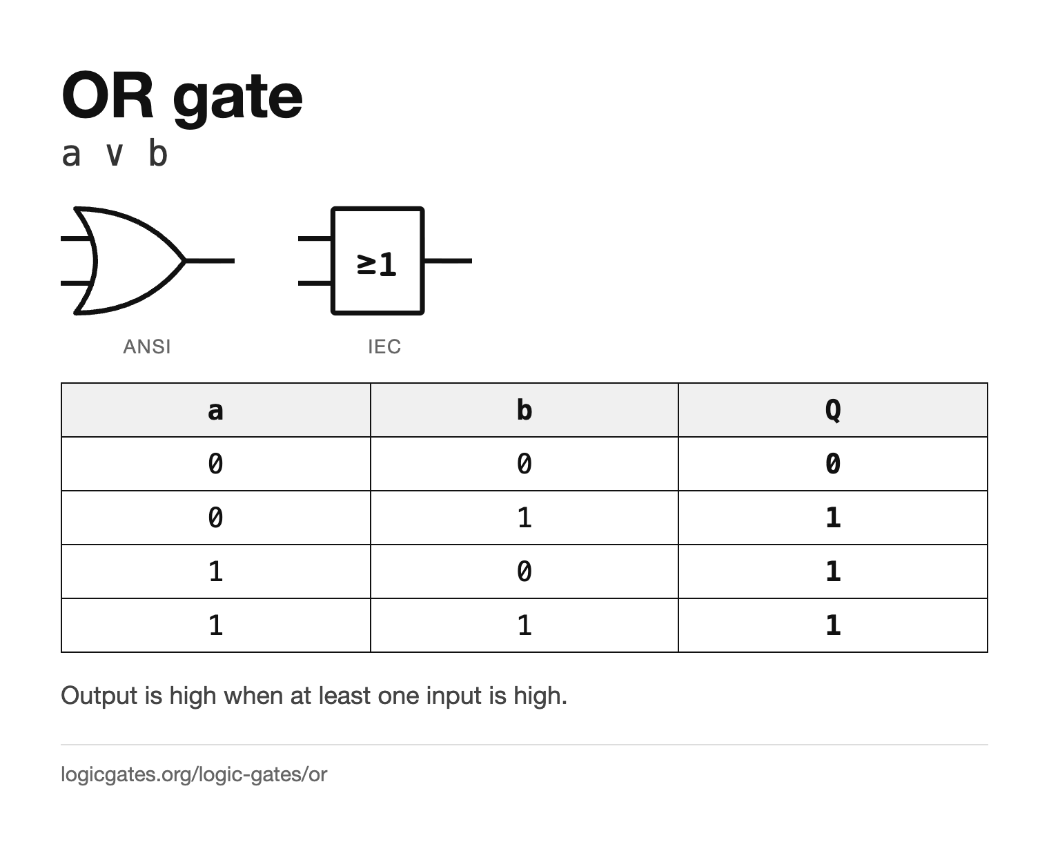
The ANSI OR symbol has a curved back and a pointed front, a little like a shield. The IEC symbol is a rectangle labelled ≥1, meaning the output is 1 when at least one input is 1. There is no bubble, since nothing is inverted. The logic gate symbols page draws all seven gates side by side in both standards.
How the OR gate works
An OR gate outputs 1 if any of its inputs is 1, and only outputs 0 when every input is 0. This is the inclusive or: unlike everyday English, "a or b" here is still true when both are true.
Two switches wired in parallel. Close either one, or both, and the current gets through; the only way to stop it is to open all of them. OR is the parallel connection to AND's series one.
3-input OR gate truth table
A 3-input OR gate outputs 1 when at least one of the three inputs is 1, so the all-zero row is the only one that gives 0. OR is associative too, so a chain of 2-input OR gates gives the same table.
| a | b | c | Inputs at 1 | Q |
|---|---|---|---|---|
| 0 | 0 | 0 | 0 | 0 |
| 0 | 0 | 1 | 1 | 1 |
| 0 | 1 | 0 | 1 | 1 |
| 0 | 1 | 1 | 2 | 1 |
| 1 | 0 | 0 | 1 | 1 |
| 1 | 0 | 1 | 2 | 1 |
| 1 | 1 | 0 | 2 | 1 |
| 1 | 1 | 1 | 3 | 1 |
Two 2-input OR gates in a chain, (a | b) | c,
give exactly this table.
OR compared with the other gates
The same four input rows through every gate, with the OR column highlighted. NOT has only one input, so its column is NOT a and ignores b.
| a | b | AND | OR | NAND | NOR | XOR | XNOR | NOT a |
|---|---|---|---|---|---|---|---|---|
| 0 | 0 | 0 | 0 | 1 | 1 | 0 | 1 | 1 |
| 0 | 1 | 0 | 1 | 1 | 0 | 1 | 0 | 1 |
| 1 | 0 | 0 | 1 | 1 | 0 | 1 | 0 | 0 |
| 1 | 1 | 1 | 1 | 0 | 0 | 0 | 1 | 0 |
- OR and XOR differ only when both inputs are 1: OR gives 1 there and XOR gives 0. That one row is the difference between inclusive and exclusive or.
- NOR is the exact opposite of OR on every row.
Building the OR gate from other gates
Each of these is equivalent to the OR gate. Paste any of them into the simulator with ctrl+E to see the circuit.
| Construction | Expression | Equals |
|---|---|---|
| From NAND gates | !(!(a & a) & !(b & b)) | a | b |
| From NOR gates | !(!(a | b) | !(a | b)) | a | b |
| De Morgan form | !(!a & !b) | a | b |
OR gate transistor circuit
In static CMOS, the textbook OR gate is a handful of transistors. Toggle the inputs to see which ones switch on and which network connects the output to the supply or to ground.
NOR: the pull-up network conducts (the PMOS transistors driven by a and b are on) and the pull-down network is open, so the NOR output is connected to VDD and is 1.
NOT: the pull-down network conducts (the NMOS driven by the NOR output is on) and the pull-up network is open, so Y is connected to GND and is 0.
A single CMOS stage always inverts, so OR is built as NOR followed by an inverter: 4 transistors plus 2. PMOS transistors, drawn with a bubble on the gate, conduct when their gate is 0; NMOS conduct when it is 1.
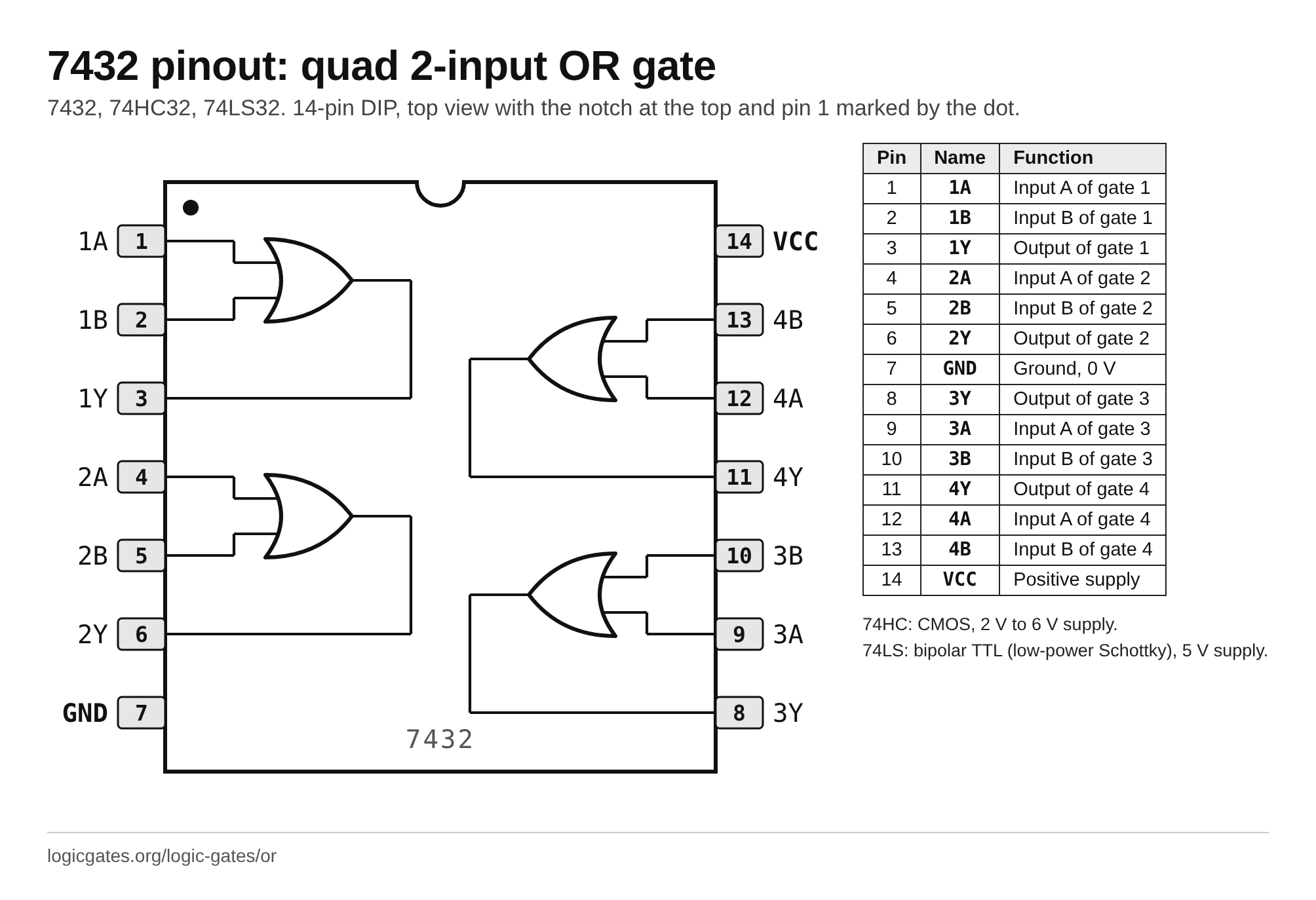
OR gate chip: the 7432 pinout
To build with real parts, the OR gate comes four to a package in the 7400 series. The 7432 is a quad 2-input OR gate.
7432, 74HC32, 74LS32: quad 2-input OR gate, 14-pin DIP
| Pin | Name | Function |
|---|---|---|
| 1 | 1A | Input A of gate 1 |
| 2 | 1B | Input B of gate 1 |
| 3 | 1Y | Output of gate 1 |
| 4 | 2A | Input A of gate 2 |
| 5 | 2B | Input B of gate 2 |
| 6 | 2Y | Output of gate 2 |
| 7 | GND | Ground, 0 V |
| 8 | 3Y | Output of gate 3 |
| 9 | 3A | Input A of gate 3 |
| 10 | 3B | Input B of gate 3 |
| 11 | 4Y | Output of gate 4 |
| 12 | 4A | Input A of gate 4 |
| 13 | 4B | Input B of gate 4 |
| 14 | VCC | Positive supply |
- 74HC: CMOS, 2 V to 6 V supply.
- 74LS: bipolar TTL (low-power Schottky), 5 V supply.
OR gate examples
Everyday and engineering things that follow the OR rule.
- A doorbell with a push button at the front door and another at the back, wired in parallel, rings when either button is pressed.
- The interior light in many cars comes on when any door is open, since each door switch can light it on its own.
- A burglar alarm goes off when any one of its sensors is triggered, or several at once.
Where the OR gate is used
- Collecting alarm or error conditions: any one of them going high raises a single combined flag.
- Bitwise OR in software, setting bits without disturbing the others.
- Merging several requests onto one line, as in a simple interrupt system.
- Building a sum of products, where the final OR joins the AND terms together.
OR gate reference card
The symbol in both standards and the truth table on one image, for notes or a slide.
 Click to download the OR reference card
In the simulator
OR sits in the Logic menu next to AND, and takes a configurable number of inputs in the same way.
Questions about the OR gate
What does an OR gate do?
It outputs 1 when at least one of its inputs is 1, and 0 only when every input is 0. A 2-input OR gate is 1 on three of its four rows.
What is the symbol for an OR gate?
In the ANSI style it is a shape with a curved back and a pointed front. In the IEC style it is a rectangle labelled ≥1.
How many inputs can an OR gate have?
Two or more. A wide OR gate outputs 1 when any input is 1, and a chain of 2-input OR gates gives the same result.
Is OR inclusive or exclusive?
Inclusive. An OR gate outputs 1 when both inputs are 1. If you want the exclusive version, which is 0 when both inputs are 1, that is the XOR gate.
What is the difference between OR and NOR?
NOR is OR with an inverted output: it gives 1 only when every input is 0.