XOR gate
High when its two inputs disagree.
XOR gate truth table
| a | b | Q |
|---|---|---|
| 0 | 0 | 0 |
| 0 | 1 | 1 |
| 1 | 0 | 1 |
| 1 | 1 | 0 |
At a glance
- Boolean expression
- a ⊻ b
- Engineering notation
- a ⊕ b
- Inputs
- Two or more
- Output is high when
- its two inputs differ
XOR gate symbol
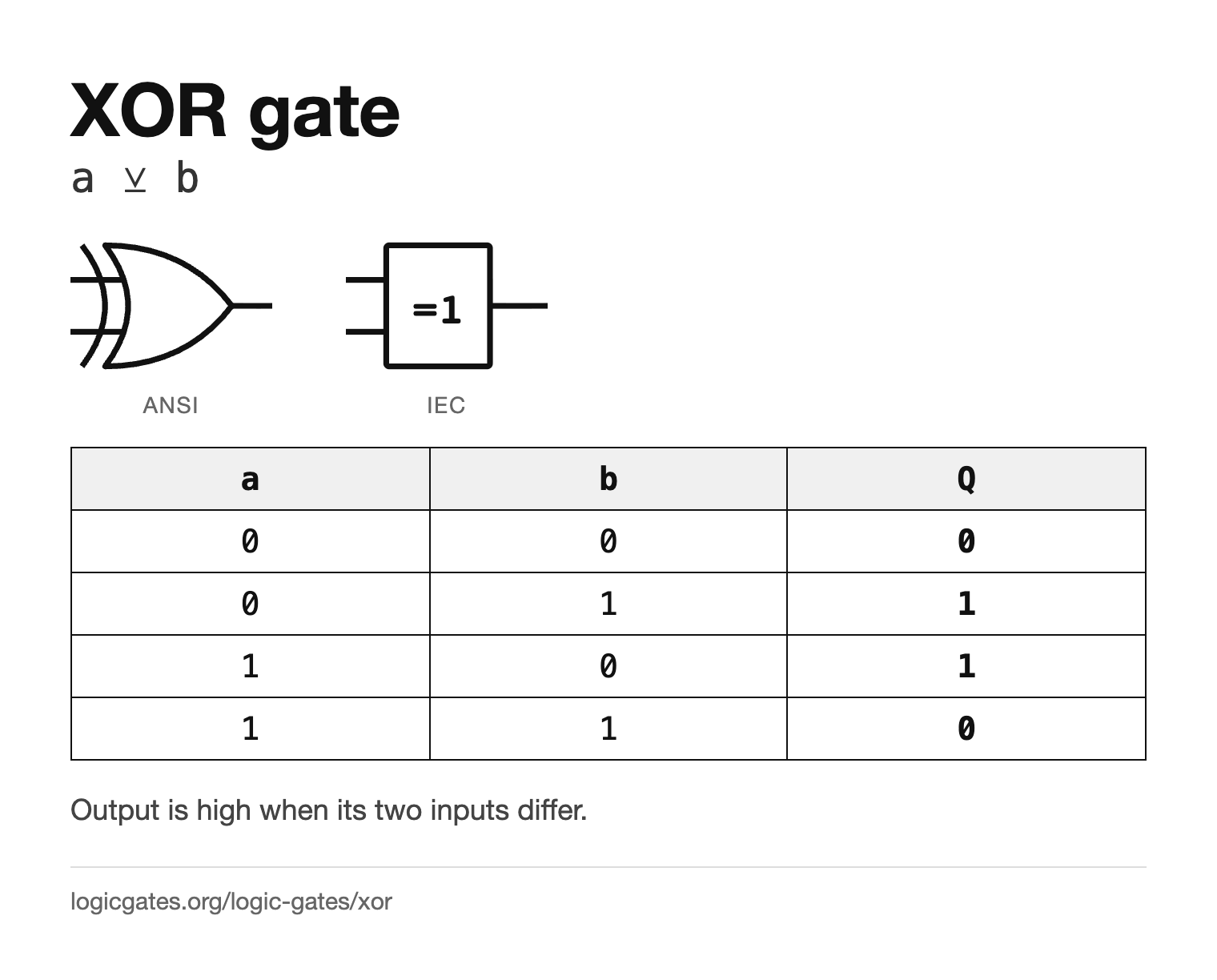
The ANSI XOR symbol is the OR shape with a second curved line drawn behind its back, across the inputs. That extra line is the only difference from OR, so it is worth looking for on a busy schematic. The IEC symbol is a rectangle labelled =1: the output is 1 when exactly one input is 1. The logic gate symbols page draws all seven gates side by side in both standards.
How the XOR gate works
An exclusive or gate outputs 1 when exactly one of its two inputs is 1. Put another way, it outputs 1 when the inputs differ and 0 when they are the same, which makes it a one bit difference detector.
XOR is the gate that answers "are these two different?". That single property explains nearly every use it has: comparing values, adding bits, flipping bits on demand and counting parity are all the same question asked in different contexts.
3-input XOR gate truth table
With three inputs, an XOR gate outputs 1 when an odd number of inputs are 1, which makes it a parity gate. That is what a chain of 2-input XOR gates gives, since each one flips the running result whenever its other input is 1, and it is what multi-input XOR parts and hardware description languages such as Verilog compute.
| a | b | c | Inputs at 1 | Q | Exactly one |
|---|---|---|---|---|---|
| 0 | 0 | 0 | 0 | 0 | 0 |
| 0 | 0 | 1 | 1 | 1 | 1 |
| 0 | 1 | 0 | 1 | 1 | 1 |
| 0 | 1 | 1 | 2 | 0 | 0 |
| 1 | 0 | 0 | 1 | 1 | 1 |
| 1 | 0 | 1 | 2 | 0 | 0 |
| 1 | 1 | 0 | 2 | 0 | 0 |
| 1 | 1 | 1 | 3 | 1 | 0 |
Two 2-input XOR gates in a chain, (a ^ b) ^ c,
give exactly this table.
Some texts define exclusive or for more than two inputs as "exactly one input is 1" instead. That one-hot function is a different gate. The IEC label =1 strictly means exactly one, which is why a multi-input parity gate is labelled 2k+1 in IEC symbols. In the table, the "exactly one" column differs from Q on row 111.
XOR compared with the other gates
The same four input rows through every gate, with the XOR column highlighted. NOT has only one input, so its column is NOT a and ignores b.
| a | b | AND | OR | NAND | NOR | XOR | XNOR | NOT a |
|---|---|---|---|---|---|---|---|---|
| 0 | 0 | 0 | 0 | 1 | 1 | 0 | 1 | 1 |
| 0 | 1 | 0 | 1 | 1 | 0 | 1 | 0 | 1 |
| 1 | 0 | 0 | 1 | 1 | 0 | 1 | 0 | 0 |
| 1 | 1 | 1 | 1 | 0 | 0 | 0 | 1 | 0 |
- XOR and OR differ only when both inputs are 1, where OR gives 1 and XOR gives 0. Mixing them up changes just that one row, which is easy to miss.
- XNOR is the exact opposite of XOR on every row.
Building the XOR gate from other gates
Each of these is equivalent to the XOR gate. Paste any of them into the simulator with ctrl+E to see the circuit.
| Construction | Expression | Equals |
|---|---|---|
| Sum of products | (a & !b) | (!a & b) | a ^ b |
| OR without the overlap | (a | b) & !(a & b) | a ^ b |
| From NAND gates only | !(!(a & !(a & b)) & !(b & !(a & b))) | a ^ b |
XOR gate transistor circuit
In static CMOS, the textbook XOR gate is a handful of transistors. Toggle the inputs to see which ones switch on and which network connects the output to the supply or to ground.
NOT a: the pull-up network conducts (the PMOS driven by a is on) and the pull-down network is open, so ¬a is connected to VDD and is 1.
NOT b: the pull-up network conducts (the PMOS driven by b is on) and the pull-down network is open, so ¬b is connected to VDD and is 1.
XOR: the pull-down network conducts (the NMOS transistors driven by ¬a and ¬b are on) and the pull-up network is open, so Y is connected to GND and is 0.
The complementary design: two inverters make ¬a and ¬b, and an 8-transistor stage pulls the output down when the inputs agree and up when they differ, 12 transistors in all. PMOS transistors, drawn with a bubble on the gate, conduct when their gate is 0; NMOS conduct when it is 1.
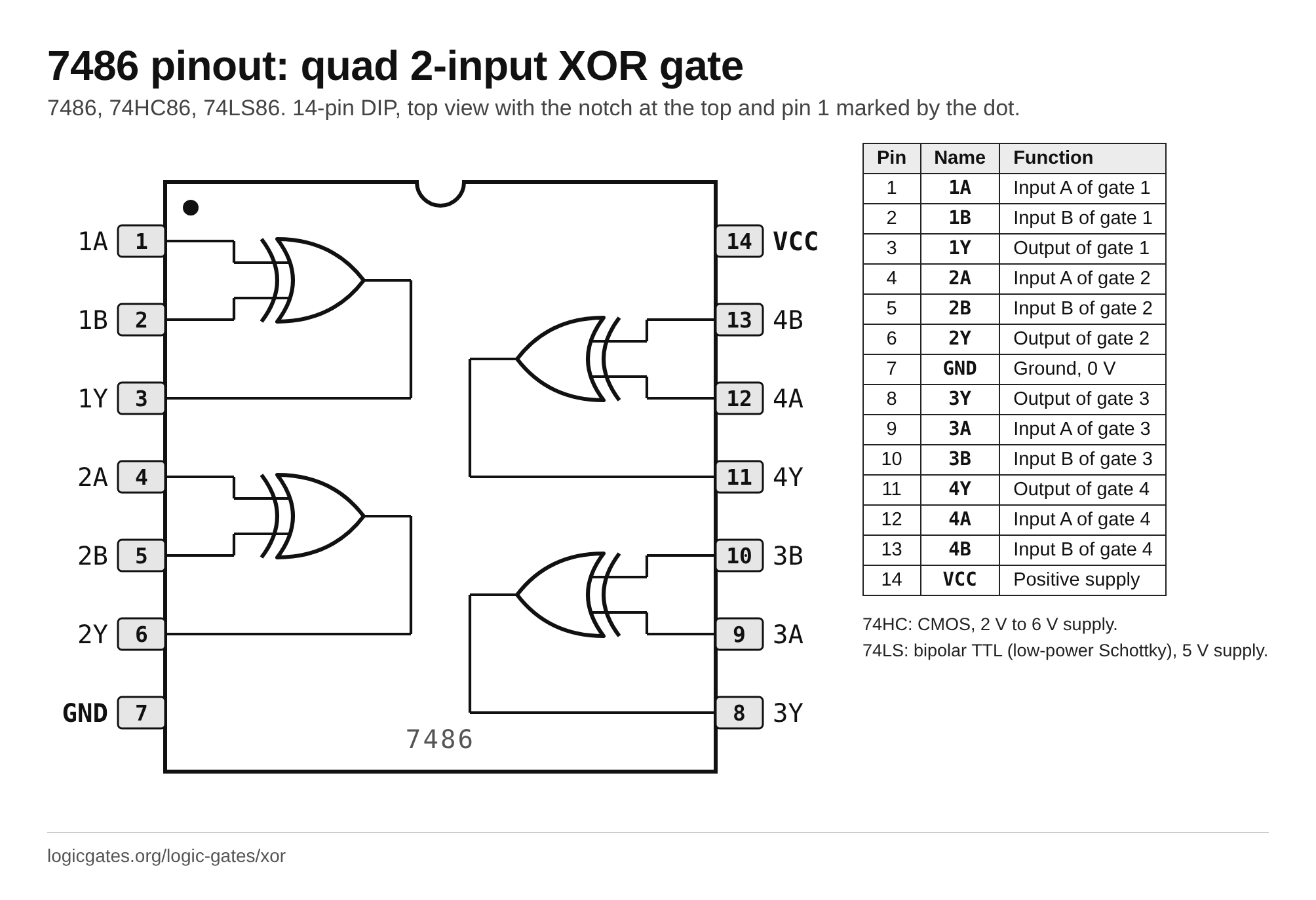
XOR gate chip: the 7486 pinout
To build with real parts, the XOR gate comes four to a package in the 7400 series. The 7486 is a quad 2-input XOR gate.
7486, 74HC86, 74LS86: quad 2-input XOR gate, 14-pin DIP
| Pin | Name | Function |
|---|---|---|
| 1 | 1A | Input A of gate 1 |
| 2 | 1B | Input B of gate 1 |
| 3 | 1Y | Output of gate 1 |
| 4 | 2A | Input A of gate 2 |
| 5 | 2B | Input B of gate 2 |
| 6 | 2Y | Output of gate 2 |
| 7 | GND | Ground, 0 V |
| 8 | 3Y | Output of gate 3 |
| 9 | 3A | Input A of gate 3 |
| 10 | 3B | Input B of gate 3 |
| 11 | 4Y | Output of gate 4 |
| 12 | 4A | Input A of gate 4 |
| 13 | 4B | Input B of gate 4 |
| 14 | VCC | Positive supply |
- 74HC: CMOS, 2 V to 6 V supply.
- 74LS: bipolar TTL (low-power Schottky), 5 V supply.
XOR gate examples
Everyday and engineering things that follow the XOR rule.
- Two-way light switches on a staircase: flipping either switch changes the light. With the switch positions labelled the right way round, the light is on when the two switches disagree.
- RAID 5 disk arrays store the XOR of the data blocks as a parity block. If one disk fails, XOR of everything that is left rebuilds its contents.
- A simple XOR cipher combines each bit of a message with a key bit; applying the same key again recovers the message, because a XOR k XOR k is a.
- Old graphics systems drew cursors and selection boxes in XOR mode, so drawing the same shape a second time erased it and restored the picture underneath.
Where the XOR gate is used
- The sum output of a half adder: 1 + 1 gives 0 and carries, which is exactly what XOR does.
- Comparing two values for equality, since a XOR b is 0 only when a and b match.
- A controlled inverter: XOR a signal with 1 to invert it, or with 0 to pass it through unchanged.
- Parity generators and checkers, and the same trick underpins the simplest error detection schemes.
XOR gate reference card
The symbol in both standards and the truth table on one image, for notes or a slide.
 Click to download the XOR reference card
In the simulator
XOR is in the Logic menu, with two inputs. For a wider parity check, chain XOR gates together: the result is 1 when an odd number of inputs are high.
Questions about the XOR gate
What does an XOR gate do?
It outputs 1 when its two inputs differ and 0 when they are the same. Put another way, the output is 1 when exactly one of the two inputs is 1.
What is the truth table of a 2-input XOR gate?
0 XOR 0 = 0, 0 XOR 1 = 1, 1 XOR 0 = 1 and 1 XOR 1 = 0. The output is 1 on the two rows where the inputs differ.
What is the symbol for an XOR gate?
In the ANSI style it is the OR symbol with an extra curved line across the inputs. In the IEC style it is a rectangle labelled =1.
How many inputs can an XOR gate have?
Two is the usual case, but wider XOR gates exist. With more than two inputs the standard meaning is parity: the output is 1 when an odd number of inputs are 1, which is also what a chain of 2-input XOR gates gives.
What is the difference between OR and XOR?
They only differ on the last row of the truth table. When both inputs are 1, OR outputs 1 and XOR outputs 0. XOR is the "one or the other, but not both" version.
Why is XOR used in adders?
Because adding two bits gives 0 for 0+0, 1 for 0+1 and 1+0, and 0 with a carry for 1+1. That pattern is exactly XOR, and the carry is exactly AND. Together they form the half adder.