The 7 types of logic gates
Every digital logic function, from a doorbell to a processor, is built out of these seven operations. Each one combines binary inputs — one for NOT, two or more for the rest — into a single binary output.
What is a logic gate?
A logic gate is a circuit with one or more inputs and one output, where every wire carries one of two values: 1 or 0, high or low, on or off. The gate applies a fixed rule to its inputs and puts the answer on its output. That is the whole idea. An AND gate's rule is "1 only if every input is 1"; a NOT gate's rule is "the opposite of the input".
Because the inputs can only be 1 or 0, a gate's behaviour can be written out in full. Two inputs give four combinations, three give eight, and a table listing the output for each is a truth table. The truth table is the gate: two circuits with the same table are interchangeable, however they are built.
And they are built in many ways. Two switches on a battery make a working AND gate: wire them in series and the lamp only lights when both are closed. Wire them in parallel and you have an OR. The first computers made the same gates from relays, then from vacuum tubes. In a diagram a gate is a symbol, and in boolean algebra it is an operator: a ∧ b and an AND gate are the same thing, written down or wired up.
From transistors to gates
In a modern chip every gate is a handful of transistors used as switches. A CMOS inverter is two of them: one connects the output to the supply when the input is low, the other connects it to ground when the input is high, so the output is always the opposite of the input. Put two of the ground-side transistors in series and the output can only be pulled low when both inputs are high: that is a NAND gate, four transistors in all. Put them in parallel instead and you get a NOR. An AND is a NAND followed by an inverter, six transistors, which is why NAND and NOR are the cheapest gates after the inverter and logic is often mapped onto them. A processor is billions of transistors, clocked billions of times a second.
Two values are used instead of ten because a circuit only has to tell "high" from "low", which it can do reliably even when the signal is noisy. Everything else, numbers, text, pictures, is encoded as strings of those bits and handled by gates a bit at a time.
On their own, gates have no memory: the output depends only on the inputs right now. Feed an output back into an input and the circuit can hold a value, which is where the SR latch, flip-flops and the rest of sequential logic begin.
Types of logic gates
Three basic gates (AND, OR, NOT), two universal gates (NAND, NOR) and two exclusive gates (XOR, XNOR). All seven at a glance, with the symbol, the boolean expression and the truth table, and a page of its own for each.
AND a ∧ b
Basic gate
| a | b | Q |
|---|---|---|
| 0 | 0 | 0 |
| 0 | 1 | 0 |
| 1 | 0 | 0 |
| 1 | 1 | 1 |
High only when every input is high.
Read more →OR a ∨ b
Basic gate
| a | b | Q |
|---|---|---|
| 0 | 0 | 0 |
| 0 | 1 | 1 |
| 1 | 0 | 1 |
| 1 | 1 | 1 |
High when at least one input is high.
Read more →NOT ¬a
Basic gate
| a | Q |
|---|---|
| 0 | 1 |
| 1 | 0 |
Outputs the opposite of its single input.
Read more →XOR a ⊻ b
Exclusive gate
| a | b | Q |
|---|---|---|
| 0 | 0 | 0 |
| 0 | 1 | 1 |
| 1 | 0 | 1 |
| 1 | 1 | 0 |
High when its two inputs disagree.
Read more →NAND ¬(a ∧ b)
Universal gate
| a | b | Q |
|---|---|---|
| 0 | 0 | 1 |
| 0 | 1 | 1 |
| 1 | 0 | 1 |
| 1 | 1 | 0 |
The inverse of AND, and enough to build everything else.
Read more →NOR ¬(a ∨ b)
Universal gate
| a | b | Q |
|---|---|---|
| 0 | 0 | 1 |
| 0 | 1 | 0 |
| 1 | 0 | 0 |
| 1 | 1 | 0 |
High only when every input is low.
Read more →XNOR ¬(a ⊻ b)
Exclusive gate
| a | b | Q |
|---|---|---|
| 0 | 0 | 1 |
| 0 | 1 | 0 |
| 1 | 0 | 0 |
| 1 | 1 | 1 |
High when its two inputs agree.
Read more →Truth table of all 7 logic gates
Every gate for the same two inputs, side by side. NOT has a single input, so its column is NOT a and ignores b.
Read down a column to see a gate's whole rule. The inverted pairs are easy to spot: NAND is AND with every output flipped, NOR is OR flipped, and XNOR is XOR flipped.
Logic gates chart
All seven with their symbols and truth tables on one image, if you want it on a wall or in a set of notes. The logic gate symbols page has a chart of both the ANSI and IEC symbols.
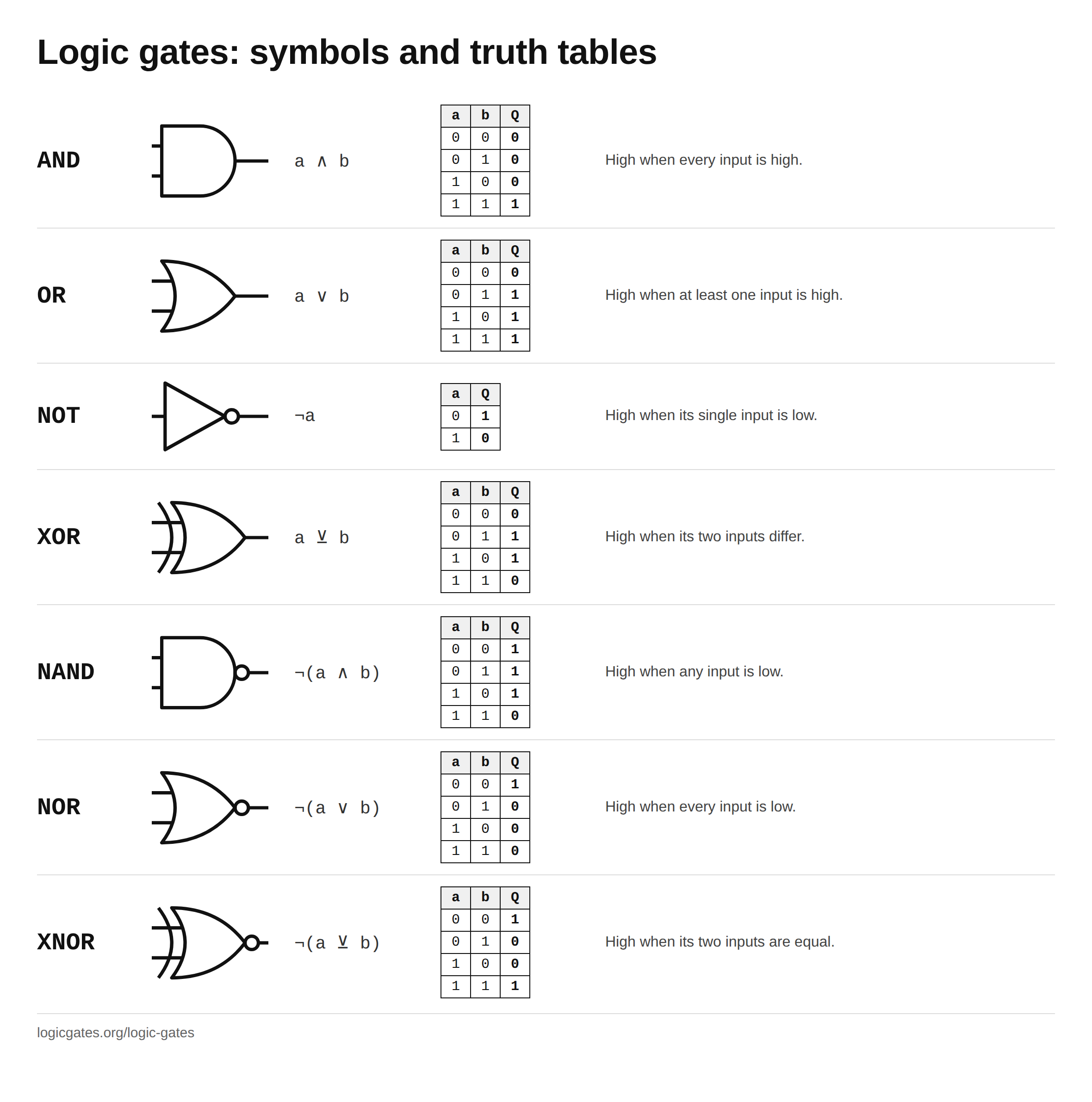 Click to download the logic gates chart
Basic gates vs universal gates
The seven are not independent. The basic gates are AND, OR and NOT: together they can express any boolean function, since every truth table can be written as an OR of AND terms, with NOT on some of the inputs. The universal gates, NAND and NOR, can do the same on their own, with no other gate needed. The exclusive gates, XOR and XNOR, are neither: they are built from the basic gates, and cannot build an AND by themselves.
| Gate | Type | Is | Inputs | Universal |
|---|---|---|---|---|
| AND | Basic | The base case: all inputs high | 2 or more | No |
| OR | Basic | The base case: any input high | 2 or more | No |
| NOT | Basic | Inversion, the thing that completes the set | 1 | No |
| XOR | Exclusive | OR, minus the case where both are high | 2 or more | No |
| NAND | Universal | AND, inverted | 2 or more | Yes |
| NOR | Universal | OR, inverted | 2 or more | Yes |
| XNOR | Exclusive | XOR, inverted | 2 or more | No |
"Universal" means every other gate can be built from that one alone. Each gate page shows the construction, and every identity on this site is machine checked against its truth table.
Universal gates: NAND and NOR
A gate is universal, or functionally complete, when every boolean function can be built from copies of it and nothing else. AND, OR and NOT together are complete, and any gate that can imitate all three is complete on its own. NAND does it in three moves:
- NOT is a NAND with its two inputs tied together: ¬(a ∧ a) = ¬a.
- AND is a NAND followed by that inverter: ¬¬(a ∧ b) = a ∧ b.
- OR is a NAND with both inputs inverted first: ¬(¬a ∧ ¬b) = a ∨ b, which is De Morgan's law.
NOR does the same with the roles of AND and OR swapped. No other two input gate qualifies: AND and OR cannot make a NOT, and XOR and XNOR cannot make an AND. This is why a single type of gate is enough, and why the Apollo Guidance Computer could be built from a single type of three input NOR gate. Every gate page shows its own NAND and NOR constructions, and the NAND and NOR converter rewrites any expression that way with the gate count.
A short history
The algebra came first. George Boole set out the arithmetic of true and false in 1847 and, in full, in The Laws of Thought in 1854, the better part of a century before anyone had a use for it in hardware. Charles Sanders Peirce saw in 1886 that electrical switches could carry it out, and Henry Sheffer showed in 1913 that a single operation is enough on its own: the Sheffer stroke, defined as NOR in his paper and usually read as NAND today. The decisive step was Claude Shannon's 1937 master's thesis, which showed that relay switching circuits and boolean algebra are the same subject: from then on a circuit could be designed by writing an expression and simplifying it. Vacuum tube logic circuits date from the 1920s and 1930s, and the first electronic computers built from them, Colossus and ENIAC, from the 1940s. Transistors followed in the 1950s, and the integrated circuits of the early 1960s put whole gates on one chip, where they have been shrinking ever since.
Questions about logic gates
What is a logic gate?
A logic gate is a small circuit that takes one or more binary inputs, each either 1 or 0, and produces a single binary output according to a fixed rule. An AND gate outputs 1 only when every input is 1; an OR gate outputs 1 when any input is 1. Its complete behaviour fits in a truth table, and in hardware each gate is a handful of transistors.
How many types of logic gates are there?
Seven: AND, OR, NOT, XOR, NAND, NOR and XNOR. Some courses stop at six and leave XNOR out, since it is XOR with the output inverted. Traditionally three are called basic, AND, OR and NOT, because the other four are combinations of those; and NAND alone, or NOR alone, can build everything.
What are the types of logic gates?
Three basic gates, AND, OR and NOT; two universal gates, NAND and NOR, which are AND and OR with the output inverted; and two exclusive gates, XOR and XNOR, which are high when the inputs differ and when they match respectively. Every one of them is defined by its truth table, shown on this page.
What are the basic logic gates?
AND, OR and NOT. Every boolean function can be written with these three alone, and the other four gates are combinations of them: NAND is AND followed by NOT, NOR is OR followed by NOT, XOR is (a ∧ ¬b) ∨ (¬a ∧ b), and XNOR is XOR followed by NOT.
What are logic gates made of?
In modern chips, transistors: a CMOS NOT gate is two of them, a NAND or NOR gate is four, and an AND gate is a NAND followed by a NOT, so six. Earlier computers built the same gates from relays and vacuum tubes, and you can make one from two switches on a battery. The rule is what matters, not the material, which is why a simulator can run the same gate as a few lines of code.
What are logic gates used for?
Everything digital. Gates add numbers, compare them, pick one signal out of several, decode addresses and drive displays. Wired back on themselves they store bits, which is how memory and counters work. A processor is billions of gates doing exactly these jobs at once.
Which logic gates are universal?
NAND and NOR, and no other two input gate. A gate is universal when every other gate can be built from copies of it alone. Tie both inputs of a NAND together and you get NOT; add that inverter to a NAND and you get AND; invert both inputs first and, by De Morgan's law, you get OR. That is what makes them universal: one well made gate covers every function. Chips favour them for a different reason, that in CMOS they are the cheapest gates after the inverter.
Who invented logic gates?
Nobody in a single step. George Boole published the algebra of true and false in 1847 and 1854. Charles Sanders Peirce noted in 1886 that electrical switches could carry out that algebra. Claude Shannon's 1937 master's thesis showed that relay circuits and boolean algebra are the same thing, which is the founding paper of digital logic design. Vacuum tube logic circuits date from the 1920s and 1930s, the first electronic computers built from them from the 1940s, transistor gates from the 1950s, and integrated circuits from the early 1960s.
What is the difference between a logic gate and boolean algebra?
They are the same thing seen two ways. Boolean algebra is the maths: variables that are 1 or 0 and operators such as AND, OR and NOT. A logic gate is that operator built as a circuit. Every boolean expression can be drawn as gates, and every gate circuit without feedback can be written as an expression.
Try them
Reading a truth table is one thing; watching a signal move is another. Drop a couple of these onto a canvas, wire them to a switch and a lamp, and toggle the inputs.
Prefer to recognise them on a schematic? The symbol reference has all seven in both the ANSI and IEC styles.
Or start from the introduction circuit, generate a truth table from what you build, and simplify it with a Karnaugh map.